


Hot streaks – more than hot air
Hot streaks –more than hot air
Task
Clarifying uncertainties whether shorter engines in aviation entail negative effects.
Solution
A numerical simulation was carried out and validated by experimental data based on three different clocking positions.
Benefit
The ideal alignment of combustion chambers to the high-pressure turbine stage avoids harmful effects.
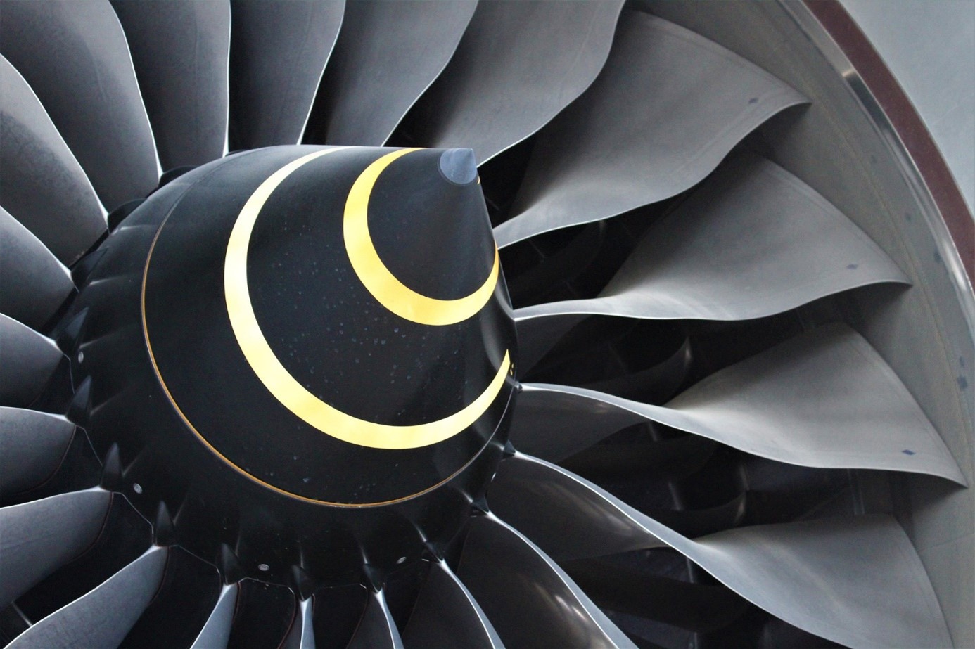
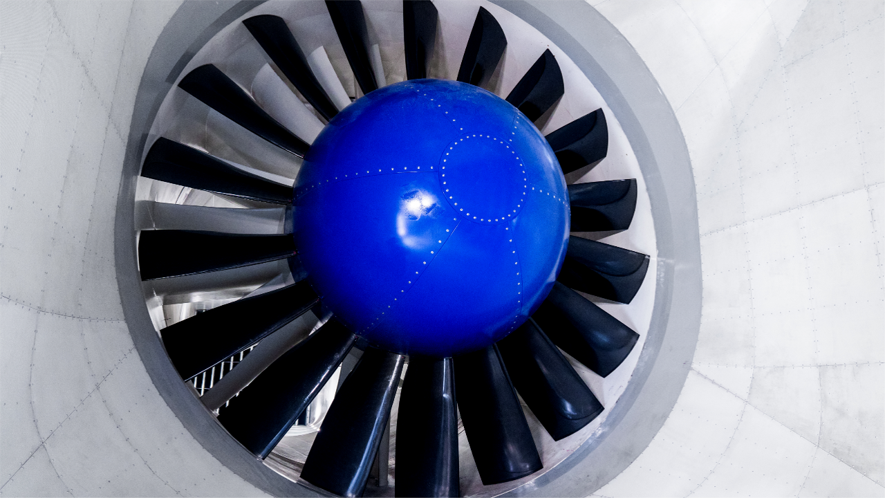
Figure 1: Aircraft turbine
Project details
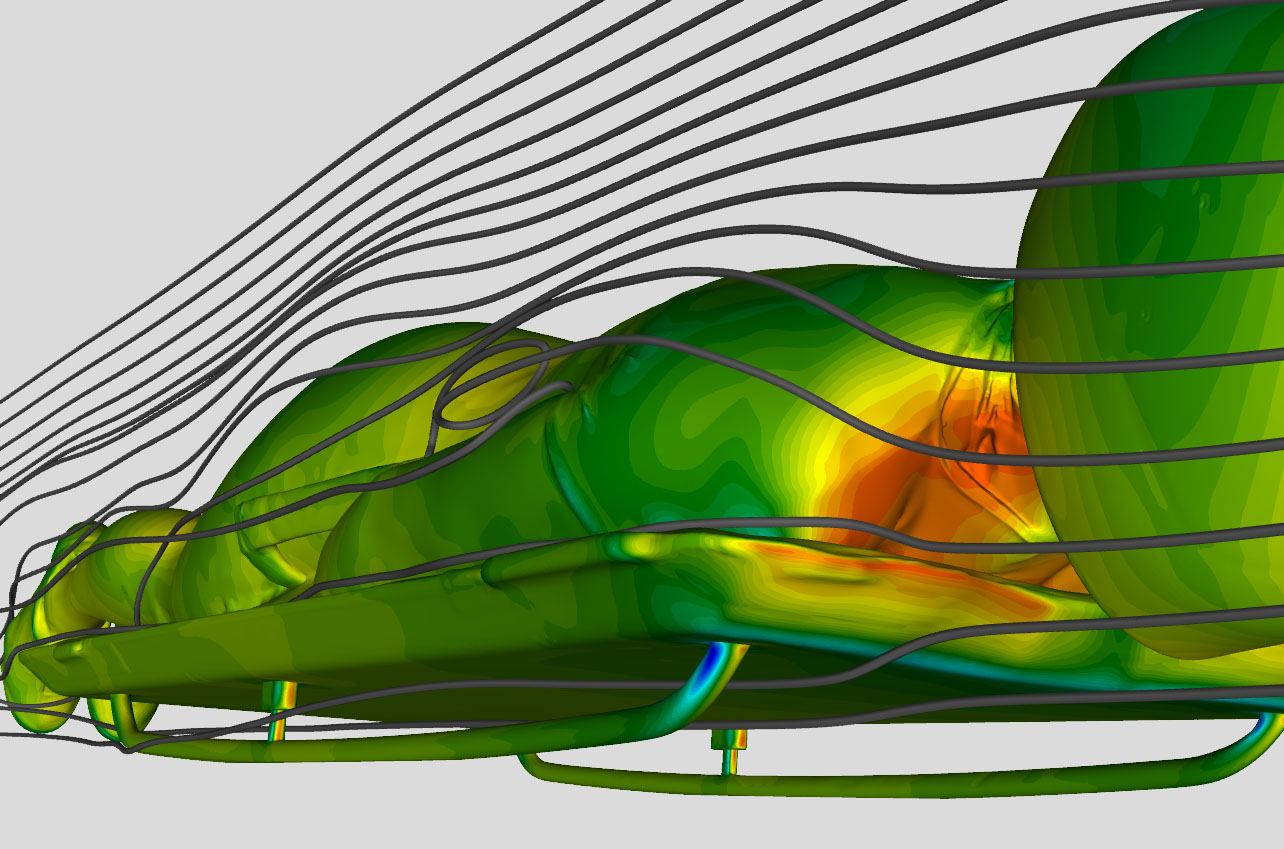
The Idomeneo project endeavors to address the changing requirements of the aeronautic industry over the course of time. Today weight reductions and fuel savings are paramount. The required weight reductions in aviation entail lightweight designs and shorter engines due to smaller axial distances between blades and vanes, which lead to shorter casing parts. As a result, the available time for hot streaks (HS) to mix out is limited. Hot streaks are non-uniform temperature distributions located downstream the combustion chambers and affect more downstream parts such as the turbine center frame (TCF). The alignment of the combustion chambers to the high-pressure turbine stage, in detail the stator vanes, influences the spatial localization of the hot streaks. The project aimed at clarifying whether changed patterns of hot streaks entail negative effects such as a faster fatigue of structures and materials and a high thermal load resulting in reduced lifetime cycles. Subsequently, an unsteady Reynolds-averaged-Navier-Stokes (URANS) simulation with SST k-omega as turbulence model was carried out by the commercial software Ansys CFX. The rotational speed of the rotor was 9609.5 rpm. The density was based on an ideal compressible gas, while the temperature-dependent viscosity was applied according to Sutherland. Furthermore, a total temperature profile was set for the simulations including hot streaks. Three different clocking positions of hot streaks relative to stator vanes were chosen to shed led on different scenarios. The entropy field at midspan highlights the migration of the hot streaks at different clocking positions as shown below.
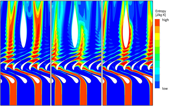
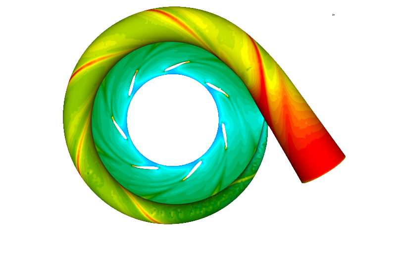
Figure 2: Different clocking positions (left: HS aligned with Stator Vane leading edge, middle: HS aligned with Stator passage, right: HS aligned with Stator vane and TCF leading edge)
On the left side the hot streak is aligned with the stator vane leading edge (clocking one). In clocking two the hot streak is aligned with the stator passage. Eventually clocking three depicts hot streaks aligned with the stator leading edges and every second hot streak is aligned with the downstream located TCF leading edge. Finally, the results were experimentally validated.
Outcome
The outcome clearly showed that the alignment of the combustion chambers to the HPT stator vanes had a remarkable impact on the aerodynamical flow. Specific spatial localizations featured particular high temperatures of hot streaks. Much evidence pointed to negative effects when those hot streaks touched the casing. Thanks to the in-depth studies realized in the context of the Idomeneo project we found evidence that an ideally aligned combustion chamber to the HPT avoids hot streaks offside the central fluidic flow. Therefore, the proper positioning of the combustion chambers is a way to avoid a high thermal load resulting in a faster fatigue of structures and materials.
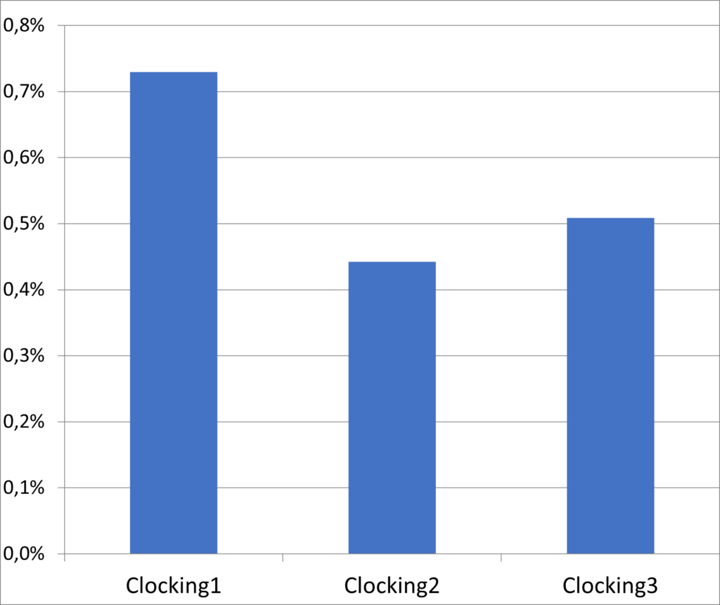
Figure 3: Results – Total pressure loss between TCF inlet and outlet