Comparison testing of different surface textures, especially Riblets produced by Nikon, to enhance the quality control.
Solution
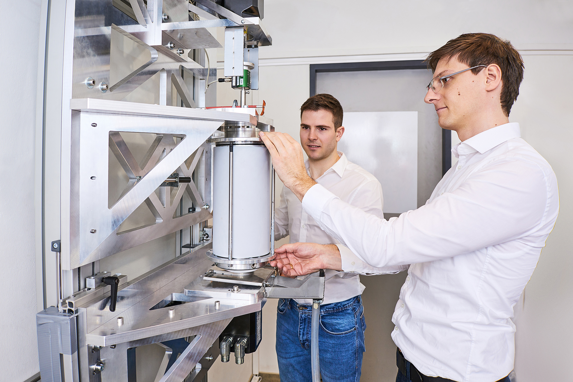
Measurement of the drag reduction curve done by the rotating test rig.
Benefit
Functionality of Riblets of different production methods; Feedback for production and data retrieval.
Figure 1: Rotating Riblet test rig
Project details
Do you know how many Riblets fit onto a cylinder of 25cm height? We have the answer: 4,100 to the point. We know it precisely as we examined it by experimentally testing Riblets for Nikon. Optimal Riblet design depends largely on the respective flow conditions (velocity, temperature, viscosity, density) and the ideal sizing is changing continuously over the flow path. Recent scientific research focused on a few main types: namely triangular Riblets, blade and trapezoidal Riblets.
However, for economical applications Riblet design is also depending on target material, target shape and design as the longitudinal grooves vary according to the intended purpose. Therefore, Nikon wanted us to test their in-house produced Riblets to get a deeper insight on the functionality of those Riblets. The collaboration between BST and Nikon enabled both companies to combine their expertise to determine optimal Riblet shapes, pitch dimensions and placement, culminating in the application of these structures directly to the surface or on a film for customers using Nikon proprietary precision-controlled free-form laser patterning.
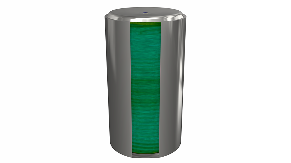
Figure 2: Simulation of the cylinder
Riblet structures vary depending on the manufacturing process. Nikon wanted to know whether the respective Riblet geometries influence the Riblet functionality to a relevant degree. To clarify that question was one of our challenges to meet. Our rotating Taylor Couette measurement system consists of two cylinders – a rotating outer cylinder (rotor) and a static cylinder (stator) on the inside. The gap in between is filled with measurement fluid. The Riblet tip-to-tip distance range is from 20 μm to 200 μm using water as testing fluid. The drag reduction curve over the rotational speed shows the specific Riblet behavior over the whole operating range. This distinct drag reduction curve is unique for each structure, size and production method and shows unambiguously the maximum drag reduction for the studied Riblet structure.
Due to the rotating test rig for Riblets, we had the possibilities to measure the viscous flow resistance to find optimal customized Riblet solutions. We supported Nikon in its efforts in designing optimal Riblet shapes for each application. The measurement of different surface structures was realized in our in-house test rig which enabled us to gather relevant information on the fluidic behavior and to fully develop the Riblet potential.
Outcome
The measurements provided data to check whether the Riblet manufacturing process was already on a good track. Furthermore, having the geometrical data of the test rig at hand the drag reduction curve of these Riblets could be compared to the Riblets of a different production method, e.g., NIL imprinted. The close cooperation between Nikon and bionic surface technologies GmbH, specialized in Riblet analysis research bore abundant fruit. The feedback on the functionality of specific Riblet structures to the manufacturing gave valuable information to exploit the potential of Riblets to the full.
Figure 3: Example of a trapeze riblet drag reduction manufactured with Roll-to-Roll technique (from the Paper “Riblet design, manufacturing, and measurements A new rapid iteration process”)