High-Flying Efficiency: Proving the Power of Cost-Effective Riblets for Aircraft Drag Reductions
High-Flying Efficiency: Proving the Power of Cost-Effective Riblets for Aircraft Drag Reductions
Task
Investigating different Riblet layouts to prove the application strategy for achieving highest performance increases at best cost-effectiveness.
Solution
Conducting profound flight tests with different Riblet layouts based on in-depth numerical Riblet analyses and CFD simulations.
Benefit
Demonstrating the effectiveness of sharkskin textured surfaces for reducing drag and increasing efficiency at a cost effective low area application.
Figure 1: Stratos 716X by Stratos Aircraft
Project details
In 2018, the aviation industry was responsible for 2,4% of the global CO2 emissions and the United Nations’ International Civil Aviation Organization (ICAO) predicted that those emissions would approximately triple by 2050. This forecast puts aircraft emissions into the spotlight, as they would account for 25% of the global carbon budget. A focal goal in the field of aviation is therefore, to significantly improve the efficiency of aircraft and lower the industry’s environmental impacts. New standards, regulatory incentives or large research fundings are frequently issued, and big research and development efforts are constantly made in this regard.
One of the most cost-effective ways to reduce the carbon footprint in the aviation industry are passive drag reduction systems. Riblet surfaces have demonstrated their potential to achieve significant drag reductions in aviation and are in this sense a highly promising technology to contribute to the efficiency progress by wide adoptions on aircraft. Research and progress on the application of Riblet surfaces on airplanes has been made since the 1990s, where 70% of an Airbus A320’s surface area was covered with Riblets and 2% of fuel savings were accomplished. However, cost-effectiveness has been a major hindrance factor since then and it has only been a few years since the technology started to mature regarding broad industrial applications. Our project concentrates on the application of Riblets on only a minor part of the plane’s area, with the goal to reach high efficiency gains with a cost-effective application strategy.
Our significant findings, which were made during this project, were published in early 2023 and will largely contribute to a broad diffusion of Riblet surface technology in commercial aviation by enhancing its cost-effectiveness. The aircraft, which was investigated over this project’s course is the Stratos 716X, developed in Redmond, Oregon, by Stratos Aircraft. It is one of the most efficient planes entering the market and a small business jet, which is a plane type never investigated before regarding Riblet surface applications.
The basis of the project were in-depth CFD (Computational Fluid Dynamic) simulations to design the plane’s Riblet layouts, assess their impact and validate the experiments. The models were designed for two different operating conditions. First, Flight Level 410 at 41.000 feet (12,500 km), which represents a typical altitude for cruise conditions of the Stratos 716X, at a velocity of 400 knots, corresponding to 0,697 Mach. Second, FL 285 at 28.500 feet(8,7 km) at 0,674 Mach.
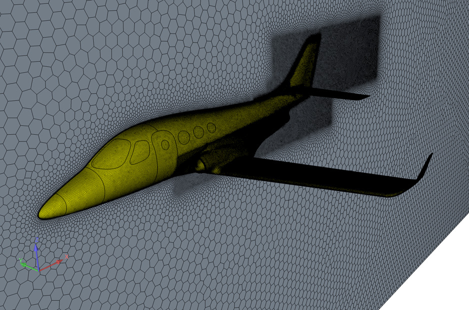
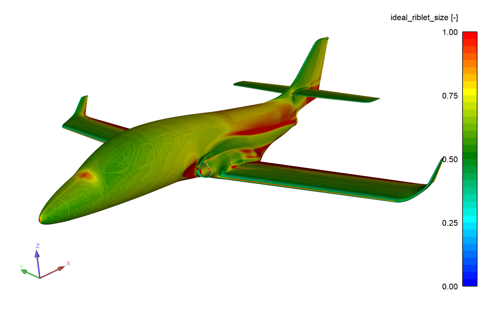
A baseline CFD simulation was necessary to have a reference for designing the Riblets. The simulations had been run in steady state with a Reynolds Averaged Navier Stokes (RANS) model, therefore, the use of only half of the numerical domain with symmetry as boundary conditions was justified. The numerical mesh (polyhedral mesh with hexahedral core) counted with 14 million cells and can be seen in Figure 2. The boundary layer was split in 15 prisms in order to capture the velocity profile close to the wall, which is crucial for an accurate Riblet design. Based on these baseline simulations and the determined wall shear stresses, the ideal Riblet geometries and allocations for maximizing their impact were designed, which can be seen in Figure 3 for FL 410.
Figure 2: Numerical Mesh
Figure 3: Ideal Riblet Size for FL410
The chosen method to apply Riblets were plastic foils, which do not enable the adaption of Riblet sizes to every surface point according to the ideal Riblet distribution (this would be enabled by the use of laser technology). Therefore, the Riblet sizes had to be discretized. After analyzing the optimal trade off, a Riblet design was chosen with only two different Riblet sizes represented by two different foil types (in Figure 5: Riblet size A : blue; Riblet size B: red). Four different Riblet layouts were examined:
Foil was applied to the entire possible Riblet area
Riblets on the wings’ Pressure Sides and Suction Sides
only on the wings’ Suction Sides and
no Riblets to obtain representative baseline measurements.
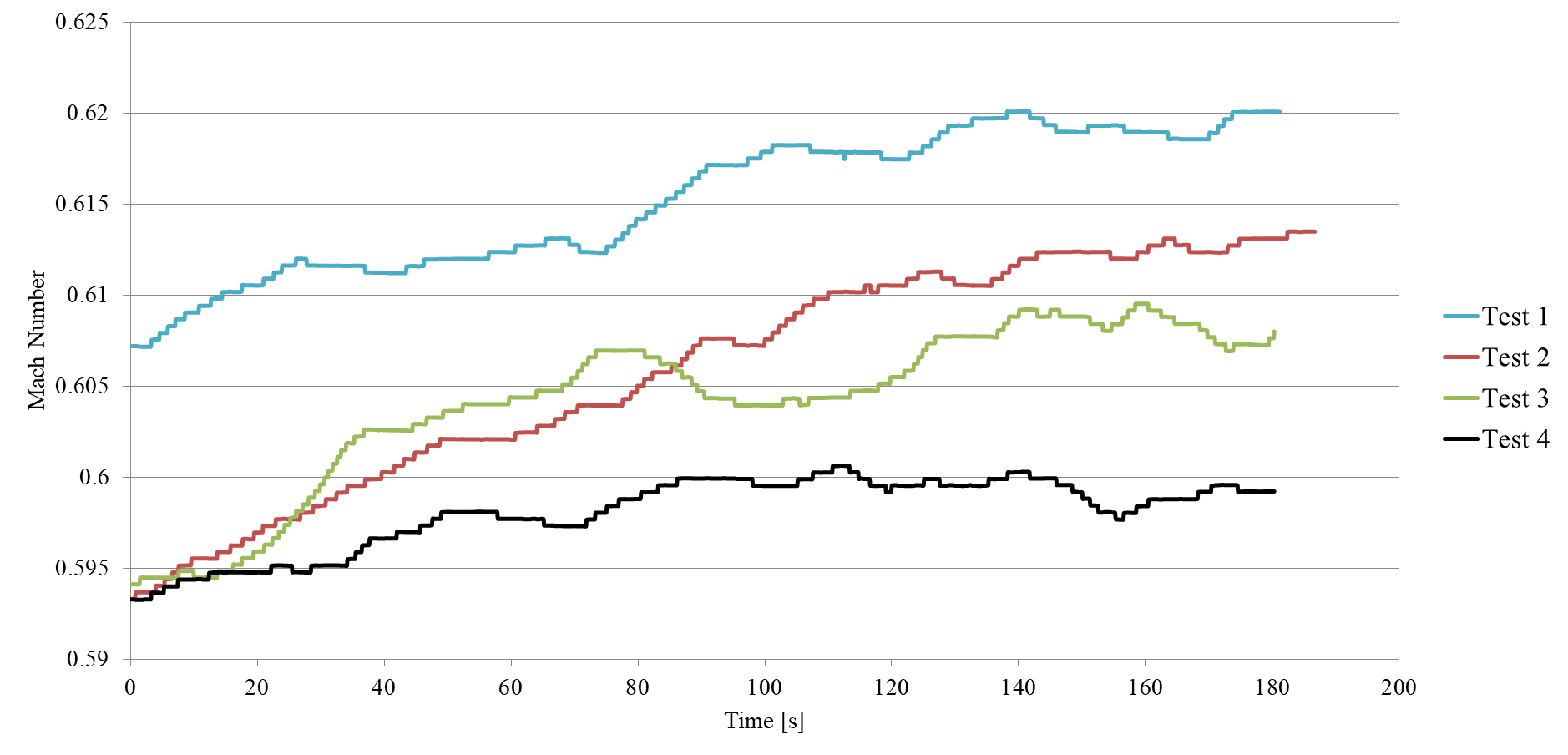
At each of the two flight levels chosen for the test’s measurements (FL410 and FL285), different cruise test points were measured: Each test point held a different parameter constant as follows:
PLA (Power Lever Angle at maximum) in order to check the maximum achievable Mach number
KIAS (Indicated Airspeed): 0,54 Mach, 313 knots for FL410; 0,4 Mach, 242 knots for FL 285
N1 (Fan Speed) at 99.5% of its maximum
ITT (Internal Turbine Temperature) at 600 [K]
Figure 4: Maximal Mach numbers achieved at FL 410 with different Riblet layouts
Outcome
Riblets show a good performance by increasing the maximal Mach number in both flight levels. The results of the PLA test at FL 410 are displayed in Figure 4, which shows that the maximal Mach number increases with the applied Riblet area. An almost 3.5% higher Mach number is reachable if the complete aircraft is covered with Riblets. When Riblets are applied only to the Suction Sides, the maximal Mach number increases up to 1.5%.
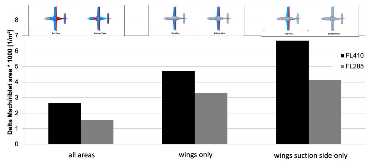
To have a clearer understanding of the Riblet impact in relation to the used surface area, Figure 5 shows the Mach number increase divided by the Riblet area. This new parameter gives an insight about the Riblet area efficiency. The smallest applied Riblet area, which is also the most economic layout, clearly shows the highest efficiency gain. The Riblet application affected the fuel consumption by a reduction of up to 3,4%, which is more than expected. However, the comparability of the KIAS tests are not certain, due to variations in the temperature and the flown speed. Therefore, no definite conclusions about the fuel consumption can be made, although a significant reduction is certain.
Figure 5: Increase of maximum Mach number in relation with the area of Riblets for the 3 Riblet configurations
This project has proven the effects of different Riblet layouts on a business jet and shows the significant possible performance increases. Further investigations will examine other cruise conditions and focus on more precise results regarding fuel savings. Moreover, the impacts of a low area Riblet application in regard of efficiency increases are demonstrated. This has significant effects on an application’s cost effectiveness and will play a major role in prospectively broad industrial deployments of Riblet surfaces.